
| Sr. No | Content | Total Hrs | % Weightage |
|---|---|---|---|
| 1 | Introduction to control problem Industrial Control examples. Mathematical models of physical systems. Control hardware and their models. Transfer function models of linear time-invariant systems. Feedback Control: Open-Loop and Closed-loop systems. Benefits of Feedback. Block diagram algebra. |
05 | 15 |
| 2 | Time Response Analysis Standard test signals. Time response of first and second order systems for standard test inputs. Application of initial and final value theorem. Design specifications for second-order systems based on the timeresponse. Concept of Stability. Routh-Hurwitz Criteria. Relative Stability analysis. Root-Locus technique. Construction of Root-loci. |
12 | 25 |
| 3 | Frequency-response analysis Relationship between time and frequency response, Polar plots, Bode plots. Nyquist stability criterion. Relative stability using Nyquist criterion – gain and phase margin. Closed-loop frequency response. |
08 | 20 |
| 4 | Introduction to Controller Design Stability, steady-state accuracy, transient accuracy, disturbance rejection, insensitivity and robustness of control systems. Root-loci method of feedback controller design. Design specifications in frequency-domain. Frequency-domain methods of design. Application of Proportional, Integral and Derivative Controllers, Lead and Lag compensation in designs. Analog and Digital implementation of controllers. |
12 | 25 |
| 5 | State variable Analysis Concepts of state variables. State space model. Diagonalization of State Matrix. Solution of state equations. Eigen values and Stability Analysis. Concept of controllability and observability. Pole-placement by state feedback. Discrete-time systems. Difference Equations. State-space models of linear discrete-time systems. Stability of linear discrete-time systems. |
06 | 15 |
Course Outcomes:
| Sr. No. | CO statement | Marks % weightage |
|---|---|---|
| CO-1 | Understand the fundamental of feedback control system. | 15 |
| CO-2 | Understand time response specifications and determine the (absolute) stability of a closed-loop control system | 25 |
| CO-3 | Determine the time and frequency-domain responses of first and second-order systems to step and other standard inputs. | 25 |
| CO-4 | Design controller as per given specifications using different techniques | 20 |
| CO-5 | Express and solve system equations in state-variable form (state variable models). | 15 |
Suggested Specification table with Marks (Theory):
| Distribution of Theory Marks |
| R Level | U Level | A Level | N Level | E Level | C Level |
| 20 | 30 | 20 | 20 | 10 | 0 |
Legends: R: Remembrance; U: Understanding; A: Application, N: Analyze and E: Evaluate C: Create and above Levels (Revised Bloom’s Taxonomy)

A control system is a system, which provides the desired response by controlling the output. The following figure shows the simple block diagram of a control system.
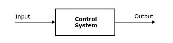
Here, the control system is represented by a single block. Since, the output is controlled by varying input, the control system got this name. We will vary this input with some mechanism. In the next section on open loop and closed loop control systems, we will study in detail about the blocks inside the control system and how to vary this input in order to get the desired response.
Examples − Traffic lights control system, washing machine
Traffic lights control system is an example of control system. Here, a sequence of input signal is applied to this control system and the output is one of the three lights that will be on for some duration of time. During this time, the other two lights will be off. Based on the traffic study at a particular junction, the on and off times of the lights can be determined. Accordingly, the input signal controls the output. So, the traffic lights control system operates on time basis.
Classification of Control Systems
Based on some parameters, we can classify the control systems into the following ways.
Continuous time and Discrete-time Control Systems
Control Systems can be classified as continuous time control systems and discrete time control systems based on the type of the signal used.
In continuous time control systems, all the signals are continuous in time. But, in discrete time control systems, there exists one or more discrete time signals.
SISO and MIMO Control Systems
Control Systems can be classified as SISO control systems and MIMO control systems based on the number of inputs and outputs present.
SISO (Single Input and Single Output) control systems have one input and one output. Whereas, MIMO (Multiple Inputs and Multiple Outputs) control systems have more than one input and more than one output.
Open Loop and Closed Loop Control Systems
Control Systems can be classified as open loop control systems and closed loop control systems based on the feedback path.
In open loop control systems, output is not fed-back to the input. So, the control action is independent of the desired output.
The following figure shows the block diagram of the open loop control system.
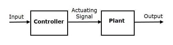
Here, an input is applied to a controller and it produces an actuating signal or controlling signal. This signal is given as an input to a plant or process which is to be controlled. So, the plant produces an output, which is controlled. The traffic lights control system which we discussed earlier is an example of an open loop control system.
In closed loop control systems, output is fed back to the input. So, the control action is dependent on the desired output.
The following figure shows the block diagram of negative feedback closed loop control system.
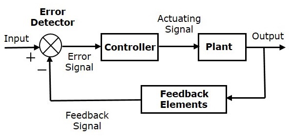
The error detector produces an error signal, which is the difference between the input and the feedback signal. This feedback signal is obtained from the block (feedback elements) by considering the output of the overall system as an input to this block. Instead of the direct input, the error signal is applied as an input to a controller.
So, the controller produces an actuating signal which controls the plant. In this combination, the output of the control system is adjusted automatically till we get the desired response. Hence, the closed loop control systems are also called the automatic control systems. Traffic lights control system having sensor at the input is an example of a closed loop control system.
The differences between the open loop and the closed loop control systems are mentioned in the following table.
| Open Loop Control Systems | Closed Loop Control Systems |
|---|---|
| Control action is independent of the desired output. | Control action is dependent of the desired output. |
| Feedback path is not present. | Feedback path is present. |
| These are also called as non-feedback control systems. | These are also called as feedback control systems. |
| Easy to design. | Difficult to design. |
| These are economical. | These are costlier. |
| Inaccurate. | Accurate. |
Comments
Post a Comment